1. Ethernet/IEEE 802.3
The second layer of the OSI reference model, the data-link layer, is represented by the IEEE 802.3 protocol, commonly known as Ethernet. The Ethernet
protocol is responsible for the basic communication between computers
on the same network. In a typical local area network (LAN), the Ethernet
implementation takes the form of the network interface adapters in the
computers and the device drivers that enable the computers to use the
adapters.
Ethernet is a packet-switching
network, meaning that the computers divide the data they want to
transmit into small pieces, called packets, and transmit them
individually over the network. When the packets reach their destination,
the receiving computer reassembles them back into their original form.
The packet-switching
concept makes it possible for a computer to run multiple network
applications simultaneously and for multiple computers to share a single
network cable.
Note:
The alternative to a packet-switching network is a circuit-switching network, in which one device establishes a physical
connection through the network to another device. The connection, or
circuit, remains open all the time that the two devices are
communicating until one or the other device terminates it. The public
telephone network is an example of a circuit-switching network.
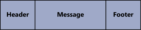
The Ethernet protocol prepares packets for transmission by encapsulating them within a frame, which consists of a header and footer, as shown in Figure 1.
The function of the frame to an Ethernet network is equivalent to that
of an envelope in a postal system. The frame contains the address of the
computer sending the packet, as well as the address of the destination
computer.
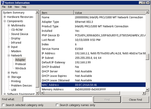
The addresses that Ethernet networks use to identify computers and other devices are called Media Access Control (MAC) addresses, or hardware addresses. A MAC
address is a 6-byte hexadecimal address that network interface adapter
manufacturers code into their hardware devices. The first three bytes
identify the manufacturer of the adapter, and the last three bytes are a
unique identifier for the individual unit. You can display the MAC
address of any Windows computer using the System Information utility, as shown in Figure 2.
Ethernet is a complicated
protocol that merits further study, but the only other issue pertinent
to a Windows SBS 2011 administrator is likely to be the complicated
terminology used to refer to Ethernet technologies. DIX
Ethernet is the name for a particular type of packet-switching LAN
technology, standardized in the 1970s by Digital Equipment Corporation,
Intel, and Xerox. To create a nonproprietary standard, the IEEE
published its first 802.3 document in 1983. The technology used today is
based on the IEEE
802.3 standards, but the term Ethernet, along with variants such as
Fast Ethernet and Gigabit Ethernet, are still in common use.
Both the DIX Ethernet and
the IEEE 802.3 standards have been modified over the years to support
different network media and ever-increasing transmission speeds. Another
common shorthand identifier for Ethernet/IEEE 802.3 networks uses the
network speed, BASE, to indicate that the network uses baseband
transmissions, and a third term that indicates something about the type
of network medium. The first of these identifiers was 10BASE5, referring
to a 10 Mb/sec baseband network with a maximum segment length of 500
meters.
Table 1 lists the designations for the most common types of UTP Ethernet networks in use today.
Table 1. Ethernet UTP Designations
| IEEE STANDARD | COMMON NAME | SHORTHAND IDENTIFIER | TRANSMISSION SPEED |
|---|
| 802.3i | Ethernet | 10BASE-T | 10 Mb/sec |
| 802.3u | Fast Ethernet | 100BASE-TX | 100 Mb/sec |
| 802.3ab | Gigabit Ethernet | 1000BASE-T | 1,000 Mb/sec |
Note:
Table 1 does not include the many types of Ethernet/IEEE
802.3 technologies designed to run on coaxial, fiber optic, and other
cable types, nor does it include standards for networking technologies
that have never been successfully introduced to market.
2. TCP/IP Basics
The third layer of the OSI reference model, the network
layer, is where you first encounter the most commonly known networking
protocols: Transmission Control Protocol/Internet Protocol (TCP/IP).
Sometimes known as the Internet protocol suite, TCP/IP is a collection
of protocols that encompass six of the seven layers of the OSI model.
The protocol that runs at the network layer, Internet
Protocol (IP), is the most important one in the suite because it
carries the messages generated by most of the other protocols.
Ethernet is a LAN
protocol, meaning that it is concerned only with transmitting data to
other computers on the local network segment. In terms of a Windows SBS
2011 network, the computers connected to your switch, or to your
wireless access point, form your LAN. IP, by contrast, is an end-to-end
protocol, meaning that it is concerned with the ultimate destination of
the message, not just the trip through the first (local) network.
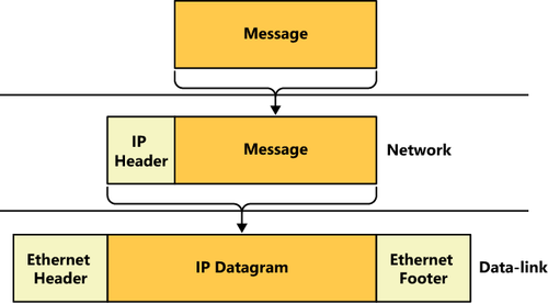
In the same way that Ethernet
uses MAC addresses to identify the recipients of its packets, IP uses
its own type of address, called an IP address. And in the same way that
Ethernet encapsulates information using a frame, IP performs its own
encapsulation, creating what is called a datagram. An IP datagram is
another envelope, with its own source and destination addresses, that
will end up inside the frame envelope created by the Ethernet
implementation, as shown in Figure 3. Although the destination address of an Ethernet frame is always the MAC address of another device on the LAN, however, the destination IP
address on the datagram in that same packet always identifies the final
recipient of the message, whether it is a computer on the LAN or an
Internet server thousands of miles away.
For example, when one of
your clients attempts to access a file on your Windows SBS server, the
Ethernet frame specifies the server’s MAC address and the IP header
contains the server’s IP address. In other words, the two are different
addresses referring to the same computer. On the other hand, when the
client uses a browser to connect to a server on the Internet, the
datagram contains the IP address of the Internet server, which is the
packet’s final destination, but the Ethernet frame contains the MAC
address of the router that provides the LAN with access to the Internet.
The two addresses point to different devices.
Because it is an end-to-end protocol, the IP address can refer to any computer, on any network,
anywhere. The MAC address, however, must point to a device on the local
network. Therefore, when the computer recognizes that the destination
IP address refers to a computer on another network, it sends the packet
to a router that provides access to other networks. The packet is then
passed along, from router to router, until it reaches the network
hosting the destination computer. Each journey from one router to
another is called a hop, and administrators frequently measure the
length of a route by the number of hops it contains.
2.1. IPv4 Addresses
As currently standardized in Internet Protocol version 4 (IPv4), IP
addresses are 32 bits long and are notated as four 8-bit decimal
numbers, separated by periods. This is sometimes called dotted decimal
notation. Because each of the 4 decimal numbers (sometimes referred to
as an octet or a quad) is 8 bits long, it can have 256 (that is 28)
possible values, ranging from 0 to 255.
A TCP/IP network consists of devices, called hosts, each of which must have a unique IP address. In a personal computer, the network interface adapter is the host, so a computer can conceivably have two hosts, and therefore two different IP addresses.
An IP address consists of
two parts: a network identifier and a host identifier. When IP routers
forward datagrams to distant locations, they use the network identifier
to locate the correct network and then use the host identifier to locate
the correct computer. Unlike MAC addresses, however, IP addresses are
not split neatly down the middle. The size of the network and host
identifiers can vary. For example, the IP standard originally used a
system called classful addressing, which specifies three address classes
with different size identifiers, as shown in Table 2.
Table 2. IP Address Classes
| CLASS | CLASS A | CLASS B | CLASS C |
|---|
| Subnet mask | 255.0.0.0 | 255.255.0.0 | 255.255.255.0 |
| Number of network identifier bits | 8 | 16 | 24 |
| Number of possible networks | 256 | 65,536 | 16,777,216 |
| Number of host identifier bits | 24 | 16 | 8 |
| Number of possible hosts per network | 16,777,214 | 65,534 | 254 |
Note:
Classes D and E exist, but are reserved only for multicast and experimental use.
To determine where the split between the network identifier and the host identifier is located, the classful
addressing system uses a value called a subnet mask. The subnet mask is
another 32-bit number that in its binary form uses 1s to represent
network bits and 0s to represent host bits. For example, the subnet mask
for a Class A IP address is 255.0.0.0, which in binary form is
11111111.00000000.00000000.00000000. The eight 1s indicate that the
first 8 bits of the accompanying IP address are the network identifier
bits, and the 24 zeroes indicate that the last 24 bits of the address
are the host identifier bits.
Note:
An IP network address (that
is, an address that includes zeroes for all its host bits) identifies
the network itself instead of a specific host on that network.
Unfortunately, the IP
addressing system is further complicated by the fact that the split
between the network and host identifier bits need not fall on one of the
8-bit boundaries. To provide greater flexibility in IP address
assignments, a system called Classless InterDomain Routing (CIDR) uses a process called variable-length subnet masking (VLSM), which enables an administrator to subdivide an IP network into smaller units, thus allocating additional bytes to the network
identifier. For example, an IP network can have 12 network identifier
bits, resulting in a subnet mask value of 255.240.0.0 (or
11111111.11110000.00000000.00000000 in binary form).
Fortunately, you don’t
have to be concerned with these complexities for the purposes of
administering a small Windows SBS 2011 network. The only element of CIDR
that you might encounter is its alternative form of notation, which
consists of a network address,
followed by a slash and the length of the network identifier. For
example, CIDR notation would use an address such as 10.0.0.0/12 to refer
to an address using the same 12 network identifier bits.
2.2. Using Private IP Addresses
To be accessible from the
Internet, a computer must have a registered IP address: an address that
some authority has assigned to that computer. This is necessary because
every computer on the Internet must have an IP address that is unique.
The ultimate authority for IP address assignments is the Internet Assigned Numbers Authority (IANA), managed by the Internet Corporation for Assigned Names and Numbers (ICANN).
However, users do not deal with IANA or ICANN directly; instead, they
obtain addresses from their ISPs or web hosting services.
The assignment of
registered IP addresses occurs on two levels, which is the primary
reason why IP addresses have a network identifier and a host
identifier. ICANN, or one of its proxies, assigns a network address to a
particular registrant, and then the administrator of the network
address assigns the host addresses to the individual computers on the
network.
Remember that this discussion
of registered addresses refers only to computers that must be accessible
to clients on the Internet, such as public web servers. You do not need
registered addresses for clients that access servers on the Internet.
For most, if not all, of the computers on your Windows SBS 2011 network,
you will use private IP addresses, which are addresses reserved for use
on unregistered networks. Table 3 lists the ranges of IP addresses that are free for use on private networks.
Table 3. Private IP Addresses
| CLASS | CLASS A | CLASS B | CLASS C |
|---|
| IP address range | 10.0.0.0 to 10.255.255.255 | 172.16.0.0 to 172.31.255.255 | 192.168.0.0 to 192.168.255.255 |
| Subnet mask | 255.0.0.0 | 255.255.0.0 | 255.255.255.0 |
| Number of addresses | 16,777,216 | 1,048,576 | 65,536 |
The primary reason for using private IP addresses is to prevent the depletion of the IPv4
address space. If every client computer accessing the Internet had a
registered IP address, the supply of addresses might run out. To enable
computers with private
IP addresses to access Internet services, routers that connect private
networks to the Internet typically use a technique called Network Address Translation (NAT). The NAT router processes all the packets sent to the Internet by computers on the private network and replaces their private
IP addresses with a single registered address. For packets arriving
from the Internet, the NAT router performs the same process in reverse.
As a result, all the computers on the private network can share a single
registered address, with the NAT router taking the responsibility for
sending the packets to the correct destinations.
Note:
The use of private IP
addresses also enhances the security of a network. Computers on the
Internet cannot address traffic to private networks directly; they must
go through a NAT router. Therefore, the only way for an attacker on the
Internet to access a computer on a private network is if the private
network computer initiates the communication. Unfortunately, these
attackers have developed clever schemes that dupe unsuspecting users
into running programs that initiate contact with attack servers on the
Internet.
2.3. IPv6
Although IPv4 is still predominant on most private networks and on the Internet, a relatively new version of the protocol, Internet
Protocol version 6 (IPv6), is gradually being introduced. The
tremendous growth of the Internet during the past decade and the
increasing use of TCP/IP for devices other than desktop computers, such
as smart phones and handheld computers, have caused experts to fear a
depletion of the existing 32-bit IP address space. IPv6
expands the address space to 128 bits, which is more than sufficiently
large to provide every device on the planet with a registered address.
This eliminates the need for private IP addresses or technologies
designed to preserve the current address space, such as NAT.
Note:
To calculate the number of possible addresses provided by a given address space, one raises 2 to the power of n (that is, 2n), where n equals the number of bits in the address space. Thus, the IPv4 address space consists of 232, or 4,294,967,296, possible addresses. By contrast, the IPv6 address space consists of 2128,
or 340,282,366,920,938,463,463,374,607,431,770,000,000 possible
addresses. This number is sufficiently large to allocate
52,351,133,372,452,071,302,057,631,913 addresses to each of the
approximately 6.5 billion people living today.
Unlike IPv4 addresses, which use decimal notation, IPv6
addresses use hexadecimals. An IPv6 address consists of eight 16-bit
(that is, 2-byte) values, separated by colons, as in the following
arrangement:
XX:XX:XX:XX:XX:XX:XX:XX
In this arrangement, each X is an 8-bit (or 1-byte) hexadecimal value, for a total of 128 bits, or 16 bytes. An example of an IPv6 address would appear as follows:
FDC0:0:0:02BD:FF:BECB:FEF4:961D
Note:
In hexadecimal notation, also known as Base
16, each digit can have 16 possible values. The traditional means of
representing this mathematically is to use the numerals 0 to 9 and the
letters A to F to represent those 16 values. Remember, an 8-bit (1-byte)
binary number can have 28, or
256, possible values. If each hexadecimal digit can have 16 values, 2
characters are needed to express the 256 possible values for each byte
of the address (162 = 256). This is why some of the 2-byte XX values in
the sample IPv6 address require 4 digits in hexadecimal notation.
To simplify an IPv6 address, you can omit the zero blocks and replace them with a double colon, as in the following example:
FDC0::02BD:FF:BECB:FEF4:961D
IPv6 addresses include network
and host identifiers like IPv4, but they do not use subnet masks;
instead, they use the same slash notation as CIDR, as in the following
example of a network address:
21CD:53::/64
Because the full network identifier is 64 bits, the expanded version of this network address is as follows:
21CD:0053:0000:0000/64
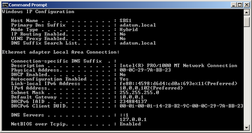
At this time, Windows
Server 2008 R2, Windows Server 2008, Windows 7, and Windows Vista all
fully support IPv6, and automatically install both the IPv4 and IPv6
clients by default. This is called a dual IP stack. When you open a Command Prompt window and execute the ipconfig /all command, you see both the IPv4 and IPv6 addresses assigned to the computer, as shown in Figure 4.
Note:
Windows Server 2003 and Windows XP include support for IPv6,
but they do not install it by default. To configure these operating
systems to use IPv6, you must manually install the Microsoft TCP/IP version 6 protocol driver in the Local Area Connection Properties sheet.
However, Internet communications
are still based on IPv4, as are Microsoft Exchange Server email
communications and those of most private networks. To accommodate both
addressing systems, Windows includes a number of transition mechanisms
that enable computers to transmit IPv6 data across IPv4 networks,
including 6to4, Intra-Site Automatic Tunnel Addressing Protocol (ISATAP), and Teredo.
These mechanisms function automatically, enabling any IPv6 applications
you might install to function properly until the transition from IPv4to
IPv6 is complete.
2.4. TCP/IP Configuration Settings
Windows computers obtain their IP addresses in one of three ways: a network
administrator can assign them manually; an automated service, such as
DHCP, can assign them; or the computers can self-assign them. Generally
speaking, manual address assignment is difficult on a network scale. You
must keep track of the addresses you have assigned to ensure that there
are no duplicates on the network. Sometimes you might have to configure
a Windows computer manually, however, and even if you never do, it is
worthwhile knowing the functions of the various configuration parameters
for the Windows TCP/IP client.
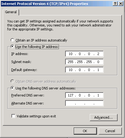
When you open the Internet Protocol Version 4 (TCP/IPv4) Properties sheet on a Windows Server 2008 computer, as shown in Figure 5, you see the following parameters:
IP Address Uniquely identifies the computer on the network
Subnet Mask Specifies which bits of the IP address form the network identifier and which bits form the host identifier
Default Gateway Specifies the IP address of a router that the computer can use to access other networks
Preferred DNS Server
Specifies the IP address of a Domain Name System (DNS) server that the
computer can use to resolve host and domain names into IP addresses
Alternate DNS Server Specifies the IP address of a second DNS server that the computer can use if the preferred DNS server is unavailable
The Internet Protocol Version 6 (TCP/IPv6) Properties sheet contains the same parameters, but with larger fields to accept the longer IPv6 addresses. As with IPv4, Windows computers can obtain IPv6 addresses from a DHCP server or through manual configuration.
IPv6 also supports stateless address autoconfiguration, in which the
computer uses router discovery messages to obtain network configuration
information from routers on the network.
All Windows computers that
load the IPv6 client by default start out by performing the stateless
address autoconfiguration process, even if they are to receive a
different address from router instructions or a DHCPv6 server later.
2.5. Static vs. Dynamic Address Configuration
When you manually configure the IP address and other TCP/IP
configuration parameters on a Windows computer, the values you assign
are permanent; they remain in place until someone manually changes them.
This is called a static IP address. When a computer obtains an IP
address from a DHCP server, it is possible for the address to change at
some future time. This is called a dynamic IP address.
Note:
A DHCP server has a pool of IP addresses, called a scope, which it leases to clients on the network
for a specific length of time, usually a matter of days. Each client
must renew its lease periodically to continue using that address. If a
client’s lease expires because the system has been turned off for an
extended period of time, the computer must obtain a new address the next
time it starts. If the old address is no longer available, the DHCP
server assigns the computer a different one.
Client computers are better off with dynamic
addresses, for several reasons. DHCP eliminates the possibility of
address duplication and enables you to add, move, and remove computers
without having to configure their TCP/IP parameters manually. However,
servers should have static IP addresses in most cases, so that clients can always locate them.
By default, your primary
Windows SBS 2011 server configures itself with a static IPv4 address on
the same network as your router if it detects a router during
installation. The server also configures itself as a DHCP server to
provide IPv4 addresses from the same network to your client computers.
However, for IPv6, all of the computers—servers and clients—assign
themselves link-local unicast addresses using stateless address
autoconfiguration.
2.6. Transport Layer Protocols
TCP, the other half of TCP/IP,
is a protocol that runs at the fourth (transport) layer of the OSI
reference model. Two primary protocols actually operate at the transport layer: TCP and User Datagram Protocol (UDP).
TCP is a connection-oriented protocol designed for the transmission of relatively large amounts of data. A connection-oriented
protocol is one in which the two computers involved in a transaction
exchange messages that establish a connection before they transmit any
application data. TCP also provides guaranteed delivery, meaning that
the receiving computer sends acknowledgments for all the data packets it
receives. The result is a highly reliable transport service, at the
cost of some additional network overhead.
When you use a web browser such as Internet Explorer to connect to a web server, the two computers establish a TCP
connection before the browser sends its Hypertext Transfer Protocol
(HTTP) request, and the server responds with a reply. The connection
establishment process confirms that the two computers are ready to send
and receive data and also enables them to perform other tasks, such as
flow control, which regulates transmission
speed. Once they have finished sending their data, the computers
exchange messages that terminate the TCP connection.
By contrast, UDP is a connectionless
protocol, which means that the computers do not exchange connection
establishment messages. UDP is intended primarily for brief transactions
that consist of a single request message and a single reply, such as
DHCP and DNS transactions. When a computer sends a message to its DNS
server to resolve a server name into an IP address, for example, the
computer transmits a single packet containing that message by using UDP
and then waits for a reply. The sending computer receives no
acknowledgment; if a reply is not forthcoming, the computer simply
resends the message. From a network traffic standpoint, this is far more efficient than transmitting connection establishment and packet acknowledgment messages that add up to more data than the original message.
Note:
Network applications also use
UDP for the transmission of large data files that are not bit-sensitive,
such as streaming audio and video. A video stream can survive the loss
of a few packets; there might be a brief interruption in the video
display, but the loss is tolerable. For this reason, a nonguaranteed
service is acceptable. When a computer is transmitting an application or
a document file, however, the loss of a single bit can render the file
unusable, so a guaranteed service such as TCP is preferable.
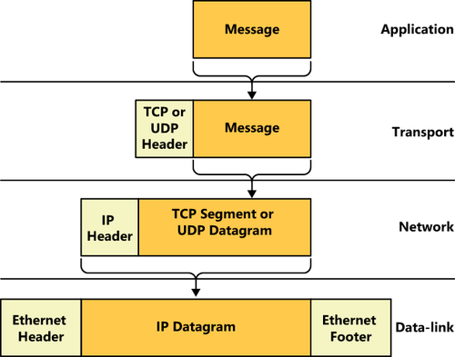
Both TCP and UDP perform
their own data encapsulations, just as IP and Ethernet do at the lower
layers of the OSI model. When an application generates a message to be
transmitted over the network, it passes it down to the appropriate transport
layer protocol, which adds its own header. A message with a TCP header
is called a segment, and as in IP, a message with a UDP header is called
a datagram. Figure 6 illustrates the entire encapsulation process a packet undergoes before transmission.
The transport
layer protocol is not involved in getting the message to the correct
destination computer; that is the job of IP and Ethernet. Instead, the
transport layer protocol header contains values called port numbers,
which identify the application that generated the message and the
application that will receive it. Therefore, while IP is responsible for
getting data packets to the correct destination computers, TCP
and UDP are responsible for getting the messages in those packets to
the correct applications running on those destination computers.
Note:
Two additional OSI model layers are located between the transport and the application layers: the session and presentation layers. No dedicated protocols operate at these layers; the transport and application layer protocols include the session and presentation layer functions.
2.7. Application Layer Protocols
At the top layer of the OSI model, the application layer, are the protocols that provide network
communication services to applications running on a computer. For
example, a web browser uses HTTP to generate messages containing
requests for a specific document on a web server. The messages travel
down through the layers of the protocol stack, out across the network,
and into the web server, in which they travel up the server’s stack to
the HTTP implementation there.
Among the protocols operating at the application layer are the following:
Hypertext Transfer Protocol (HTTP) A protocol that web browsers and web servers use to exchange request and reply messages
Dynamic Host Configuration Protocol (DHCP) A protocol and service that automatically assigns IP addresses and other configuration settings to network clients
Domain Name System (DNS) A protocol and service that computers use to resolve domain and host names into IP addresses
Simple Mail Transfer Protocol (SMTP) A protocol that email clients and servers use to transmit messages
Post Office Protocol (POP) A protocol and service that maintains mailboxes for email clients and enables them to download their messages
Internet Message Access Protocol (IMAP) A protocol and service that maintains mailboxes for email clients and enables them to store their messages on a server
File Transfer Protocol (FTP) A protocol that enables clients to transfer files to and from servers, and to perform basic file management tasks
Telnet A protocol that enables clients to log on to a server and execute programs from the command prompt